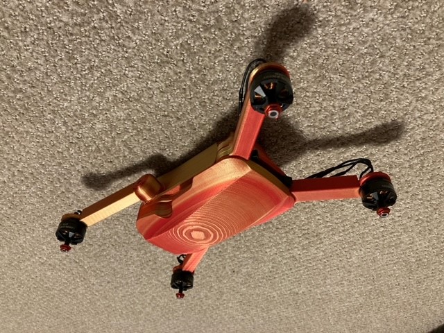
Another project that was sparked during Covid, I decided that I wanted to build something that could fly. This idea eventually grew into a custom quadcopter build. From the beginning I knew that I wanted to build this project from scratch; that meant designing and building a custom body, and coding the flight controller instead of using a factory model. It also meant that there would be a large amount of crashes as I tried to get this drone (named Geoff) into the air.
These constraints laid the groundwork one of the most difficult and fulfilling projects that I have worked on.
There are plenty of resources online that talk about all the parts needed to put together a drone. I knew early on that I wanted to control this drone with an Arduino at the core. Then I spent the first part of this project researching all the details I could find on electronics specs, motor power outputs, optimized propeller sizes, and power systems. I made some weight and power calculations until I was happy with my choices and ordered the goods.
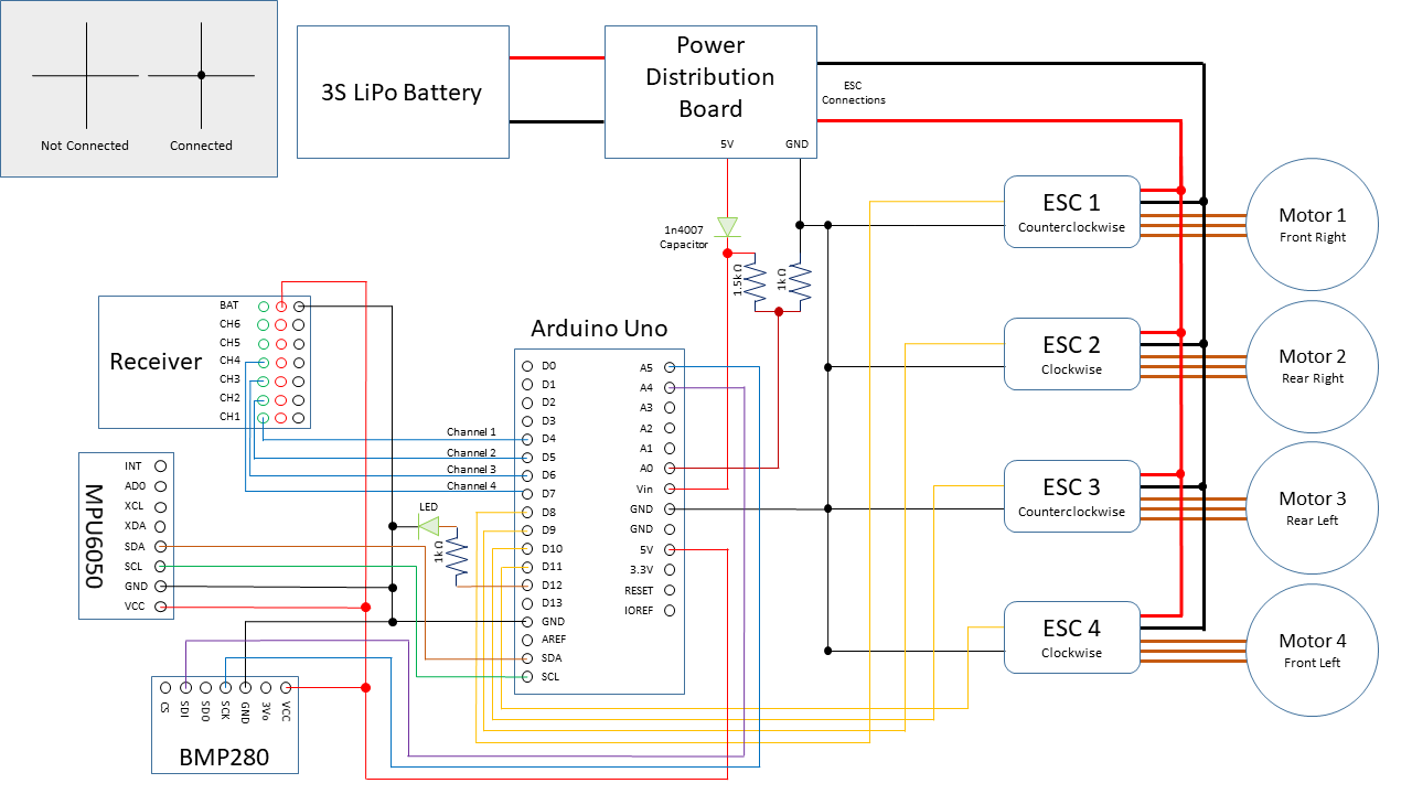
To integrate the electronics into a compact space, I soldered a custom circuit board that connected directly to the Arduino Uno I was using. This board housed all connections with the motors, sensors, transmitters, and power system. On the right, here is the wiring schematic for the drone.
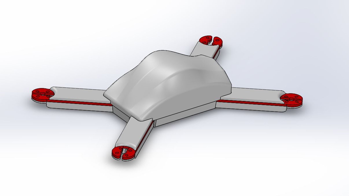
While I wired the electronics system, I also started modeling the body and arms. The drone measures 300mm from opposing propellers. The central body of the drone has three layers built in for the electronics. A 3 cell Lipo battery is strapped to the base of the body. Above that, the power distribution board connects the Lipo battery to the Arduino and the motor controllers. Another layer up is where the Arduino sits with the receiver, accelerometer/gyro, and barometer. The four electronic speed controllers that send signal to the motors sit snuggly into the underside of the arms. To cover the electronics, a cover can snap on with an opening in the back to connect to the Arduino.
The entire body of the drone was 3D printed with a Prusa MK2s.
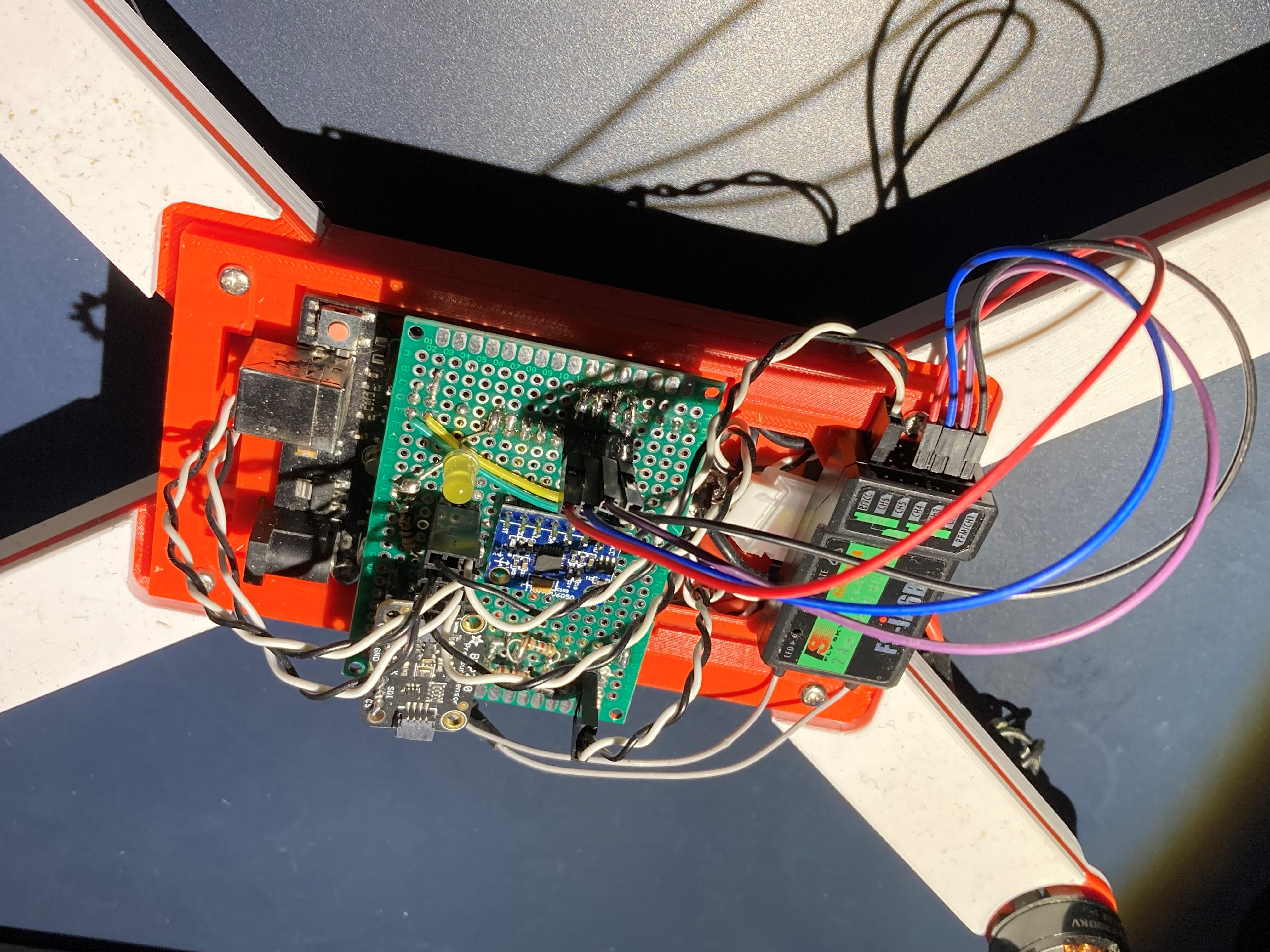
The Arduino flight controller code was inspired by Joop Brokking's YMFC auto leveling quadcopter. Many modifications were made along the way as this project expanded in different directions. The flight controller uses several PID controllers to maintain a steady position in the air. An MPU6050 chip is used to monitor the orientation of the drone in the sky. The first set of PIDs reacts to these changes and adjusts the motor pulses to allow for a smooth flight. A second PID is set up using a BMP barometer chip to calculate the height of the drone. This allows the drone to maintain a steady altitude when flying.
You can check out the code here.
This is a project that may continue indefinitely as more and more ideas emerge. My initial goal was to create a flying machine and Geoff has been able to surpass expectations. The altitude sensing capability was the first major addition to the project after I got it off the ground. I have also considered adding a camera in the future.
Check back later to see more about how Geoff has developed.